
Wind Turbine Yaw Controls: Part 2
Let’s take a closer look at some of the sensors used in the yaw control system. Potentiometers,
encoders and ultrasonic sensors may be used to detect wind direction.
A potentiometer is a variable resistor consisting of a resistive strip, 3 terminals, and a movable wiper. The movable wind vane is connected to the wiper. As the wind direction changes, the vane moves the wiper across the resistive element, and the output of the potentiometer changes in proportion to the wind’s movement.

If a voltage is applied to the end terminals of the potentiometer, the output at the wiper will be a variable voltage suitable as an input to a controller.
Sensors using potentiometers provide excellent linearity, simplicity, continuous output, and low cost. Disadvantages include wiper wear that requires periodic replacement, a dead band gap as the wiper crosses from point A to point B, and susceptibility to icing. Heaters and correct design can reduce icing problems.

Some directional vane sensors use an encoder instead of a potentiometer. An encoder consists of a coded, perforated disk, several light sources, which are usually light-emitting diodes, and corresponding light detectors. A binary bit is produced when light passes through the disk and the detector is activated. When each bit is grouped with bits from the other encoder tracks, absolute encoders can create many different binary position codes. Every code has a unique value that matches a position within the encoder’s 360 degrees of rotation.

Many encoders used as wind direction detectors use a disk constructed with a special binary code called a gray code. Gray code is used because each change of position changes only one bit of the code. This makes data transmission more reliable. The 4-bit gray code disk shown divides the nacelle’s 360° of rotation into 16 parts. Each section represents twenty-two point five degrees.
To increase the encoder’s resolution, more tracks and more bits are used. A typical 8-bit gray code disk divides a rotation into 256 parts for a resolution of about one point four-one degrees.

Another kind of sensor, the ultrasonic anemometer, uses sound waves to measure both wind direction and speed. This sensor measures the time taken for an ultrasonic pulse to travel from one transducer to the opposite transducer, and then compares it with the time taken for another pulse to travel in the opposite direction. Likewise, differences are measured between other pairs of transducers. By comparing the time it takes for sound to travel between probe tips, the direction of wind travel can be calculated. If the wind is blowing in the same direction as the pulse, the pulse will travel faster. Wind blowing against the pulse will slow it down.

Ultrasonic devices do not have any dead band, and icing is not a problem because there are no moving mechanical parts.
To keep the turbine pointed into the wind, the controller compares the wind direction to the direction of the nacelle. A yaw position sensor sends this nacelle directional information to the controller. Yaw position sensors may use several different sensor technologies, including incremental encoders, limit switches, and proximity sensors.
An incremental encoder is similar to the absolute encoder described previously, except that instead of many light sources and detectors, it only needs one, two, or three source and detector pairs. These are arranged in concentric tracks around the disk’s perimeter.
If the encoder has only one track, the sensor’s output will be a series of on/off pulses. If there are 8 on/off pulses for every rotation of the encoder, each pulse represents 45° of rotation.
Increasing the number of pulses per revolution will improve the encoder’s resolution. For example, 360 pulses per revolution yields a resolution of 1 degree. By counting the number of pulses produced, the controller may calculate how far the nacelle has yawed.

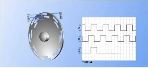
A single track encoder may measure distance traveled, but not the direction of travel. To determine direction, a second light source and detector track is added to the encoder. The second track is offset from the first track as shown. By monitoring which sensor turns on first, the controller can determine if the yaw is clockwise or counterclockwise.

In this example, if the nacelle yaws clockwise, pulse B will turn on before pulse A. If the nacelle yaws counterclockwise, pulse A will turn on before pulse B. Encoders with two tracks are called quadrature encoders because they produce four times the resolution of an encoder with a single track and the same number of pulses per revolution.
If desired, a third track with a single pulse, called track Z, may be added. This track may be used to produce one pulse for each complete revolution of the encoder wheel. The Z track is often used to reset pulse counters each revolution.
In use, the encoder disk is turned by a gear that meshes with the yaw ring teeth as shown. Since the encoder disk will rotate many times for each complete rotation of the nacelle, the controller will be able to determine the nacelle’s position with a high degree of accuracy.

Some yaw position sensors combine encoders with limit switches to detect nacelle rotation, and also alert the controller of cable twist problems

A limit switch is a mechanical switch that is actuated by physical contact with a target, such as a cam or other moving object.
In the yaw position sensor, the same gear that rotates the encoder shaft also rotates a set of internal gears to turn the cams that activate the limit switches. Gear ratios of 150:1 are typical of yaw position limit switch mechanisms.
Limit switches may be connected to any voltage, AC or DC. They do not consume any power, and they are easy to install and adjust. Most limit switches have both normally open and normally closed contacts available.

Proximity sensors, sometimes called prox sensors, are also used in wind turbine yaw control applications. They detect metallic targets like hydraulic cylinders, gear teeth, cams or other moving metal equipment
Inductive prox sensors are designed to emit an oscillating magnetic field. When a metallic target enters the field, the target absorbs some of the field energy, and the oscillations stop. This action triggers a switching circuit connected to the controller. Thus, when a target is sensed, the controller receives a signal that the target is in place.

Prox sensors are often used in place of limit switches because they are solid state, switch faster than a mechanical limit switch, and do not need to physically touch the target. Because there are no mechanical contacts, they do not wear out or cause sparking. However, the target must come within a few millimeters of the sensor face to be detected.
Unlike a limit switch that can be wired to any voltage level or type, a prox sensor must be connected only to a voltage type and level that match its requirements

There are prox switches made specifically for AC voltages, or different DC polarities, but they are not interchangeable.
In all cases, the manufacturer’s manuals should be consulted to determine how to select, install, align, and calibrate nacelle yaw position sensors.


Highland Community College as part of WindTechTV.org